|
|
|
Usuarios conectados
Actualmente hay 5858 visitantes online. |
|
Productos
|
|
Información
|
|
Destacado
|
|
|
 |
|
|
No hay comentarios de productos.
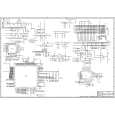
2 SMALL SIGNAL PART WITH STV2248:
STV2248 video processor is essential for realizing all small signal functions for a color TV receiver.
2.1 Vision IF Amplifier3 The vision IF amplifier can demodulate signals with positive and negative modulation. The PLL demodulator is completely alignment-free. Although the VCO (Toko-coil) of the PLL circuit is external, yet the frequency is fixed to the required value by the original manufacturer thus the Toko-coil does not need to be adjusted manually. The setting of the various frequencies (38.9 or 45.75 MHz) can be made via changing the coil itself. 2.2 QSS Sound Circuit (QSS Versions) The sound IF amplifier is similar to the vision IF amplifier and has an external AGC de-coupling capacitor. The single reference QSS mixer is realised by a multiplier. In this multiplier the SIF signal is converted to the inter-carrier frequency by mixing it with the regenerated picture carrier from the VCO. The mixer output signal is supplied to the output via a high-pass filter for attenuation of the residual video signals. With this system a high performance hi-fi stereo sound processing can be achieved. The AM sound demodulator is realised by a multiplier. The modulated sound IF signal is multiplied in phase with the limited SIF signal. The demodulator output signal is supplied to the output via a low-pass filter for attenuation of the carrier harmonics. The AM signal is supplied to the output via the volume control. 2.3. AM DEMODULATOR The AM demodulated signal results from multiplying the input signal by itself, it is available on AM/FM output. 2.4 FM Demodulator and Audio Amplifier (Mono Versions): The FM demodulator is realized as narrow-band PLL with external loop filter, which provides the necessary selectivity without using an external band-pass filter. To obtain a good selectivity a linear phase detector and constant input signal amplitude are required. For this reason the inter-carrier signal is internally supplied to the demodulator via a gain controlled amplifier and AGC circuit. The nominal frequency of the demodulator is tuned to the required frequency (4.5/ 5.5/6.0/6.5 MHz) by means of a calibration circuit that uses the clock frequency of the µ-controller/Teletext decoder as a reference. The setting to the wanted frequency is realized by means of the software. It can be read whether the PLL frequency is inside or outside the window and whether the PLL is in lock or not. With this information it is possible to make an automatic search system for the incoming sound frequency. This is realized by means of a software loop that alternate the demodulator to various frequencies, then select the frequency on which a lock condition has been found. De-emphasis output signal amplitude is independent of the TV standard and has the same value for a frequency deviation of ±25 kHz at the 4.5 MHz standard and for a deviation of ±50 kHz for the other standards. When the IF circuit is switched to positive modulation the internal signal on de-emphasis pin is automatically muted. The audio control circuit contains an audio switch and volume control. In the mono inter-carrier sound versions the Automatic Volume Leveling (AVL) function can be activated. The pin to which the external capacitor has to be connected depends on the IC version. For the 90° types the capacitor is connected to the EW output pin (pin 20). When the AVL is active it automatically stabilizes the audio output signal to a certain level. 2.5 Video Switching The video processor (STV2248C) has three CVBS inputs and two RGB inputs. The first CVBS input is used for external CVBS from SCART 1, the second is used for either CVBS from FAV, and the third one is used for internal video. The selection between both external video inputs signals is realized by means of software switches.
2.6 Synchronization Circuit
The video processor (STV224X) performs the horizontal and vertical processing. The external horizontal deflection circuit is controlled via the Horizontal output pulse (HOUT). The vertical scanning is performed through an external ramp generator and a vertical power amplifier IC controlled by the Vertical output pulse (VOUT). The main components of the deflection circuit are: � PLL1: the first phase locked loop that locks the internal line frequency reference on the CVBS input signal. It is composed of an integrated VCO (12 MHz) that requires the chroma Reference frequency (4.43MHz or 3.58MHz crystal oscillator reference signal), a divider by 768, a line decoder, and a phase comparator. � PLL2: The second phase locked loop that controls the phase of the horizontal output (Compensation of horizontal deflection transistor storage time variation). Also the horizontal position adjustment is also performed in PLL2. � A vertical pulse extractor. � A vertical countdown system to generate all vertical windows (vertical synchronization window, frame blanking pulses, 50/ 60Hz identification window...). � Automatic identification of 50/60Hz scanning. � PLL1 time constant control. � Noise detector, video identification circuits, and horizontal coincidence detector. � Vertical output stage including de-interlace function, vertical position control. � Vertical amplitude control voltage output (combined with chroma reference output and Xtal 1 indication).
3
|
|
|
> |
|